


Categories List
4-in-1 Laser Welding Machines for Stainless Steel: Heat and Distortion Control
A stainless steel panel can look straight in the fixture, then pull out of shape as soon as the clamps come off. On thin sheet, a little extra dwell time can also turn a clean seam into a dark heat mark or a hole. These problems are frustrating because increasing power is rarely the answer.
For operators using a 4 in 1 laser welding machine for stainless steel, consistent results depend on balancing travel speed, joint fit-up, beam settings, shielding gas, and weld sequence. RISTEC’s focus on precision-engineered laser equipment supports that approach: machine capability matters, but repeatable preparation and controlled heat input determine what leaves the workbench.
Read the part before changing the power
Austenitic stainless steels such as 304 and 316 expand considerably when heated and conduct heat less readily than carbon steel. Heat concentrates around the joint, while the surrounding cooler material restrains expansion. As the weld contracts, that uneven strain can produce bowing, angular distortion, or rippling.
Before welding, identify the material grade, thickness, joint type, and dimensional tolerance. A long butt joint in a thin decorative panel behaves differently from a short corner seam in a rigid enclosure. Duplex and other stainless grades may also require specific thermal controls; do not transfer a 304 setup without checking the applicable procedure.
Look closely at the joint itself. A variable gap makes the operator slow down or add energy to bridge it, creating local hot spots. For autogenous welding, where no filler is added, close and consistent fit-up is especially important. If a gap requires filler, use a qualified filler-assisted process rather than trying to wash both edges together with extra heat.
Set up a representative test, not a convenient scrap
Use test pieces that match the production material, thickness, surface condition, joint geometry, and clamping arrangement. A setting that works on a small, heavily supported coupon may distort a large unsupported panel.
Establish a baseline from the equipment manufacturer’s process guidance or an approved welding procedure. Then change one variable at a time. Keep a simple record of power, travel speed, focus position, wobble settings where available, gas conditions, and the resulting weld quality.
Balance energy against travel speed
As a practical guide, nominal energy per unit length rises with laser power and falls as travel speed increases. However, this relationship alone does not predict penetration: focus, beam distribution, joint condition, and material absorption also matter.
- If the seam overheats: check for slow travel, hesitation, excessive overlap, or repeated passes before reducing power.
- If fusion is incomplete: verify joint alignment, focus, cleanliness, and travel consistency before adding energy.
- If burn-through occurs: inspect for an open gap or unsupported edge as well as excessive energy input.
Use the lowest energy input that consistently achieves the required fusion and weld profile—not simply the lowest power setting. Too little energy can leave an attractive seam with incomplete fusion beneath it. Evaluate test welds using inspection appropriate to the application; appearance alone cannot confirm penetration.
Keep focus and wobble under control
Maintain the specified working distance and torch orientation. Variations in standoff change how energy reaches the joint, making a stable recipe behave unpredictably. Follow the head manufacturer’s instructions rather than using deliberate defocus as a universal cooling technique.
If the welding head supports beam wobble, a wider pattern distributes energy over a broader area. That can help accommodate certain joints, but it may reduce penetration at unchanged power and speed. Increasing power to compensate can enlarge the heated zone. Match wobble width and frequency to the joint instead of assuming a wider seam is safer.
Keep the sheet stable without trapping excessive stress
Good fixturing holds the joint in alignment while allowing a planned welding sequence. Poor fixturing either lets edges lift or forces the assembly into position under heavy preload. In the second case, the part may spring out of tolerance after release even when it looked satisfactory during welding.
Use clean supports and clamps positioned to prevent local separation. Approved backing or heat-sinking arrangements can help manage thin edges, but their material, contact, and placement must be compatible with the process. Avoid improvised arrangements that introduce contamination or unsafe laser reflections.
Tack welding is part of heat control, not merely assembly preparation. Place tacks to maintain a uniform gap, using a balanced sequence rather than pulling the joint progressively in one direction. Keep tacks sound and small enough for the intended finishing pass.
For long seams, consider short sections, skip welding, or a back-step sequence when permitted by the drawing and welding procedure. Alternate between separated areas to reduce concentrated heating. Where a continuous sealed seam is required, plan section overlaps carefully: repeated heating at every restart can create defects and visible marks.
Allow cooling between operations when needed, and check temperature consistently rather than judging by touch. Avoid unapproved water quenching or direct air blasts, which can introduce uneven cooling, contamination, or shielding disruption.
Discoloration is a clue—not a complete diagnosis
A dark weld does not automatically mean the power is too high. Heat tint develops when hot stainless steel reacts with oxygen, so poor shielding can produce discoloration even when the thermal settings are otherwise reasonable.
Use the shielding gas specified for the material and procedure. Argon is common, but gas selection should not be treated as interchangeable across all stainless applications. Check gas purity, leaks, nozzle condition, coverage, and drafts. Excessive flow can create turbulence and draw surrounding air into the shielding zone.
For full-penetration joints with exposed roots, backside shielding may be necessary to prevent heavy root oxidation, often called sugaring. A clean face does not prove that the underside is protected.
Use the multifunction system without carrying contamination forward
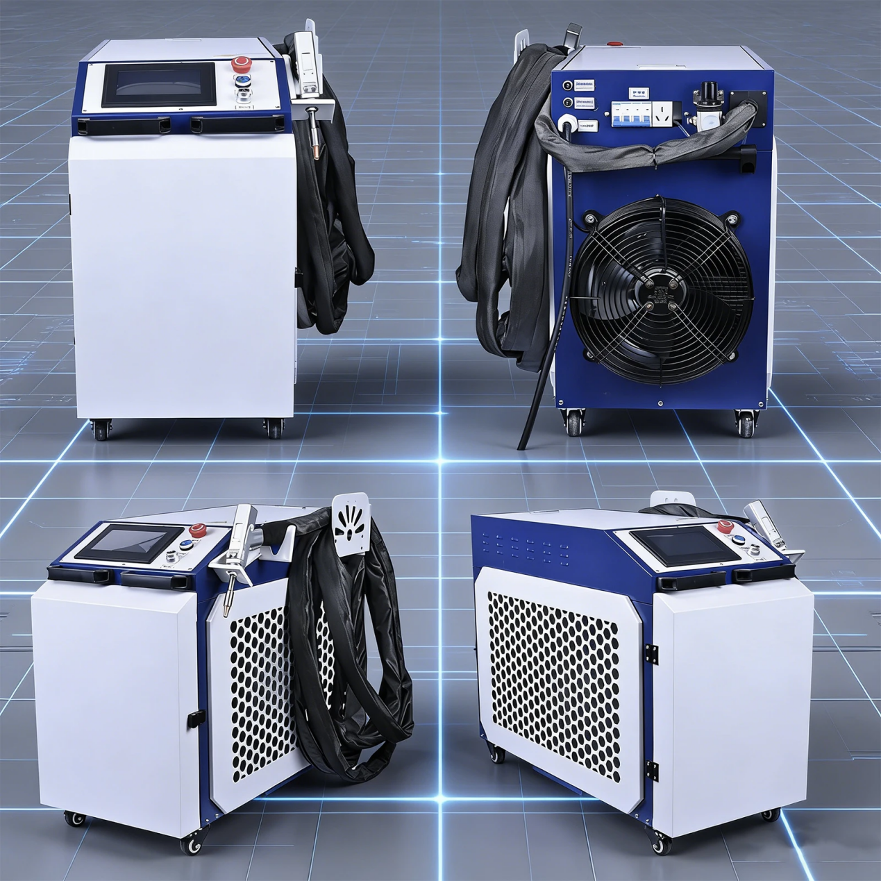
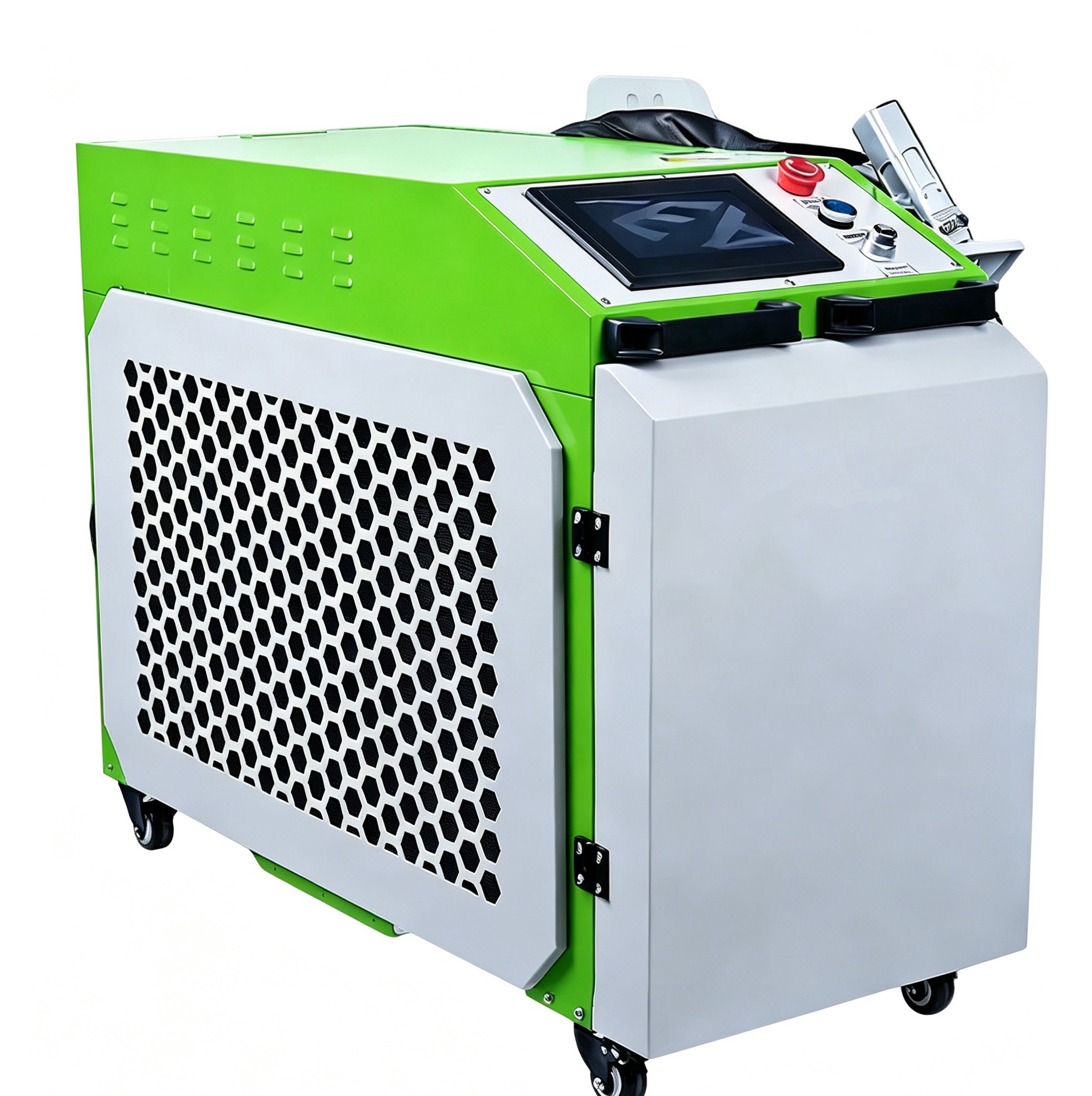
A 4 in 1 laser welding machine for stainless steel can support several workshop operations, but the exact functions and changeover requirements depend on the configuration. When evaluating RISTEC’s 4 in 1 fiber laser welding machine, confirm the supplied head, supported modes, consumables, and stainless welding process guidance for your application.
If laser cleaning is part of the configured system, validate it on the actual surface before production. Cleaning can remove certain contaminants, but it is not automatically a substitute for proper degreasing or oxide removal. Excessive cleaning exposure can also heat thin sheet before welding begins.
Keep stainless preparation tools separate from carbon-steel tools to avoid embedded iron contamination. After mode changes, verify the correct nozzle, optics condition, gas arrangement, and process selection. Do not assume the last successful welding setup remains active.
Make the first acceptable seam repeatable
Once a test weld meets the requirements, record more than the machine settings. Include clamp positions, tack spacing, sequence, torch orientation, and acceptance checks. For manual welding, consistent hand speed and support are essential; a guide or suitable positioning aid may reduce variation on long seams.
Inspect dimensions after cooling and fixture release. Where corrosion resistance or hygienic service matters, specify suitable post-weld cleaning and surface treatment; removing visible tint alone does not establish acceptance.
All trials must take place within the required laser-controlled work area, using suitable protective measures, wavelength-appropriate eyewear, fume extraction, and trained operators. Stainless welding fumes and reflected laser energy remain hazards even during a short test.
The goal is not the fastest-looking pass. It is a stable process that produces sound fusion, acceptable surfaces, and a part that stays within tolerance after cooling. Control the joint, motion, shielding, and sequence together, and power adjustments become smaller, more predictable decisions.
Leave A Reply
Get real-time quotes
Interested? Leave your contact details.