


Categories List
How Often Should an ATC CNC Router Be Calibrated for Repeatable Cabinet Production?
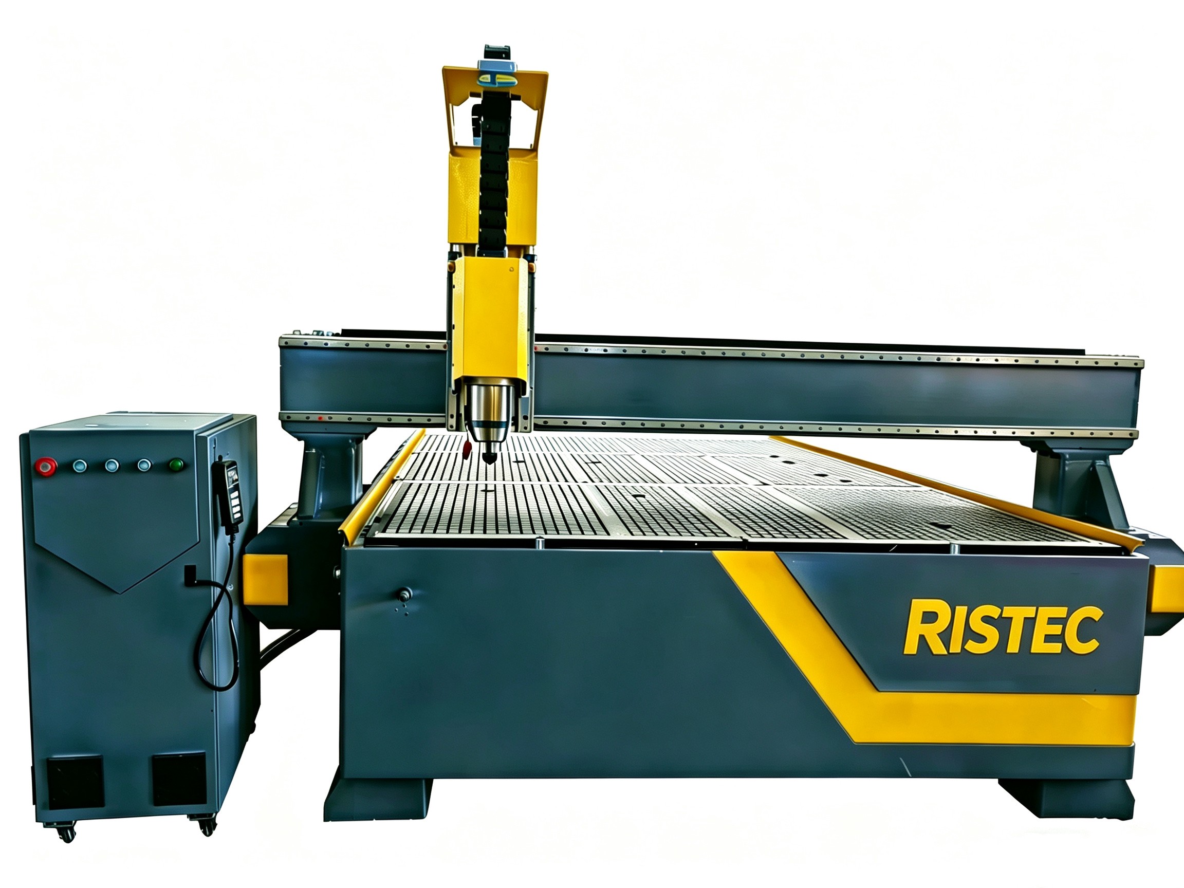
For repeatable cabinet production, an ATC CNC router should not be placed on a single “calibrate every six months” schedule. A more defensible control system is verification-led: confirm critical functions at the start of each shift or production run, perform documented intermediate checks weekly or monthly according to workload and tolerance requirements, and carry out a full geometric and ATC calibration after defined trigger events or at planned intervals.
The practical answer to How often should ATC CNC router machine be calibrated? is therefore: as often as the process needs to prove that it remains capable of meeting the cabinet plant’s dimensional, assembly, and safety requirements. A router cutting one-off panels in a low-volume workshop does not face the same control burden as a nested-based manufacturing cell producing cabinet components across multiple shifts with automated tool changes.
In cabinet work, small deviations can become visible only downstream. A slight X/Y positioning error may create inconsistent dowel-hole spacing. A tool-length offset problem can leave hinge cups shallow or drill-through features incomplete. ATC pickup inconsistency can cause a cutter to machine at the wrong Z height, while spindle or collet runout can reduce edge quality long before a nominal size check reveals the underlying cause. Calibration is therefore not simply about restoring machine geometry; it is about controlling the entire chain between the program, the selected tool, the workholding condition, and the finished component.
Calibration and routine verification are not the same activity
A common weakness in router maintenance records is treating every inspection as “calibration.” This makes records look complete while obscuring whether the machine’s actual accuracy has been established against a known reference.
Calibration is the controlled measurement and adjustment of machine-related parameters against traceable or suitably verified references. Depending on the machine and available metrology equipment, this can include axis positioning accuracy, backlash or reversal error, squareness, spindle alignment, tool-change position, tool-length measurement, and Z-axis reference consistency.
Verification is the more frequent confirmation that the machine is still producing acceptable results. It may involve machining a test panel, measuring a defined hole pattern, checking a tool probe repeatability sequence, confirming an ATC tool pickup, or comparing actual dimensions with programmed values. Verification does not always require adjustment. Its purpose is to detect drift before nonconforming cabinet parts accumulate.
For quality control, the distinction matters because a passed daily test piece does not prove that the router’s full geometric condition is within specification. Conversely, a full annual laser-interferometer assessment does not protect production if the tool probe, collet, or ATC carousel has changed condition during the week.
A frequency model that reflects cabinet-production risk
The following intervals are working control ranges rather than universal machine-maker requirements. The machine manufacturer’s instructions, the documented production tolerance, the customer’s quality requirements, and applicable workplace safety rules should always govern the final schedule.
For a high-volume cabinet line, the “full” calibration interval may need to be shorter than twelve months if verification records show drift, if machines run extended shifts, or if cabinet construction uses tight location tolerances for drilling, dowels, connectors, or hardware. By contrast, a lightly used router may not need frequent geometry adjustment, but it still requires regular verification because toolholding and probing faults can arise independently of axis wear.
It is usually more useful to classify calibration frequency by process risk than by elapsed calendar time. A router used for rough trimming oversized MDF sheets has a different failure consequence from a router machining five-piece door parts, hinge patterns, drawer-system bores, or ready-to-assemble connectors. The more a downstream assembly depends on positional consistency, the more frequently the process should be checked.
The events that should trigger calibration before the planned date
A fixed interval must never become permission to ignore a change in machine behavior. Certain events warrant an immediate verification and, where results require it, a targeted calibration before routine production resumes.
- A crash, collision, tool breakage event, or program error that loads the spindle, gantry, tool changer, or fixture unexpectedly.
- Replacement or adjustment of spindle, servo motor, gearbox, ballscrew, rack-and-pinion drive, linear guide, encoder, tool probe, collet system, ATC gripper, or carousel mechanism.
- Machine relocation, foundation work, major levelling adjustment, or significant change to the supporting floor condition.
- Repeated tool-change alarms, incomplete tool seating, unexplained tool-length differences, or visible inconsistency after automatic tool changes.
- A sustained rise in dimensional corrections at assembly, especially when the same correction appears across different programs or material batches.
- New programs introducing tighter feature-location tolerances or deeper dependence on multi-tool operations.
- Changes in environmental conditions that affect the machine structure, material conditioning, dust extraction performance, or electrical stability.
Not every trigger demands a complete geometric survey. A collision involving only a damaged probe may justify focused checks of probe repeatability, Z zero, spindle nose condition, and the affected tool station. A gantry impact or machine move calls for a broader assessment of axis alignment, squareness, and positioning performance. The response should match the credible failure mode rather than applying the same checklist to every incident.
ATC calibration requires more than checking axis dimensions
On a manual-tool-change router, an inaccurate cut may be traced mainly to tool offset, work offset, axis positioning, or workholding. An ATC router adds additional transfer points where error can enter the process. The machine may position correctly at the panel but still produce an out-of-spec part because the wrong tool was loaded, the tool was not fully seated, the offset was measured incorrectly, or the toolholder condition changed between jobs.
Critical ATC-related checks include:
- Toolholder seating and taper cleanliness. Dust, resin, chips, corrosion, or damage on the taper can affect concentricity and tool length. Cleaning should be controlled and documented where it is part of the production quality plan.
- Collet and nut condition. Worn, cracked, contaminated, or incorrectly assembled collets contribute to runout and poor retention. The cutting tool can appear acceptable in a static inspection but move under routing load.
- Spindle runout. Excessive runout affects cutter life, edge finish, bore quality, and dimensional consistency. It should be checked with an appropriate indicator and method at the spindle interface and, when needed, with the actual tool assembly.
- Tool-length measurement repeatability. The probe must be clean, securely mounted, and checked using a repeatable reference tool or controlled routine. A single successful probe cycle is not evidence of repeatability.
- Carousel or rack position. Tool stations must present holders consistently at the pickup point. Misalignment can create intermittent faults that are difficult to identify from finished parts alone.
- Tool clamp and release function. Pneumatic condition, drawbar operation, gripper wear, and sensor status are both quality and safety concerns. A tool that is not retained correctly can create a serious hazard.
ATC calibration should also verify the logic connecting physical tools to control data. Tool number, diameter, length, rotation direction, feed parameters, and expected tool type must match the actual holder location. A machine can be geometrically accurate and still machine a cabinet component incorrectly if a tool library entry has been edited without a controlled approval process.
Use production features, not only machine diagnostics, to define acceptable accuracy
Machine-controller diagnostics can identify alarms and servo-related issues, but cabinet quality is determined by features that must fit together. A useful verification artifact is a controlled test panel containing the operations that matter most to the plant: line bores, shelf-pin patterns, dowel holes, hinge cups, connector bores, dados, rectangular cutouts, and outside-profile dimensions.
The test panel should have defined nominal dimensions, a stated measurement method, acceptance limits, revision control, and a documented response when results fall outside limits. It should be made using the same material category, tooling arrangement, vacuum strategy, and machining sequence that represent normal production. A test pattern cut in a small piece of stable material may fail to reveal movement that occurs when machining a full sheet with variable flatness or insufficient vacuum support.
For dimensional checks, a quality plan should separate machine error from material behavior. MDF, particleboard, plywood, laminated board, and solid-wood components do not respond identically to cutting forces, moisture conditions, internal stress, or sheet flatness. If a hole pattern is consistent but the outer profile varies after panel release, the investigation may need to examine material movement and workholding rather than immediately changing axis compensation.
Likewise, a spoilboard that is no longer surfaced flat relative to the machine coordinate system can mimic Z-axis inaccuracy. The issue may appear as variable pocket depth, incomplete cut-through, or inconsistent engraving depth across the sheet. Surfacing the spoilboard is not a substitute for checking Z-axis accuracy, but it is often necessary before Z-related verification results can be interpreted correctly.
Measurement discipline matters as much as the interval
A calibration schedule is only credible when the measurement system is capable of detecting the deviation of concern. Checking a 0.2 mm cabinet-feature tolerance with an unsuitable tape measure or poorly controlled handheld method will not establish process capability. The reference tool, gauges, indicators, test artifacts, and measuring instruments should be selected for the required tolerance and maintained under the organization’s measurement-control procedures.
International machine-tool test methods can provide useful technical references. The ISO 230 series addresses test codes for machine tools, including geometric accuracy and positioning performance. ISO 230-2 is commonly referenced for determining positioning accuracy and repeatability of numerically controlled machine axes. These standards help define how a test can be conducted, but they do not automatically define the acceptable production tolerance for a particular cabinet component. Acceptance limits must still be set in relation to the part drawing, joint design, hardware requirements, and process capability expectations.
Safety checks should not be separated from accuracy checks. An ATC system with uncertain tool retention, damaged holders, unreliable sensors, or improper manual intervention presents a risk even if the latest dimensional test panel passed. Guarding, interlocks, emergency stops, dust extraction, pneumatic isolation, lockout procedures, and tool-change access must be maintained in accordance with the router manufacturer’s instructions and applicable machinery safety requirements. Any calibration work requiring access inside guarded areas should be performed only under controlled maintenance conditions.
Records should show drift, not merely completed maintenance
A maintenance log that says “machine calibrated” is of limited value after a quality dispute. A stronger record identifies the date, machine identification, operating hours where available, reason for the check, instruments used, test conditions, measured results, adjustments made, person responsible, and approval for release back to production.
Trend records are especially valuable. If X-axis results slowly move in one direction, if Z offsets require increasingly frequent correction, or if a particular tool station repeatedly produces runout-related defects, the pattern supports preventive action before failures become widespread. The useful question is not only whether the machine passed today, but whether its condition is becoming less stable.
The same traceability principle applies when assessing other CNC assets, including a large Size ground rail Sheet Laser Cutter: accuracy claims and acceptance checks have value only when the measured parameters, references, operating conditions, and release criteria are clear. Different machine types require different test methods, but undocumented “precision” is not a quality-control system.
For repeatable cabinet production, the most reliable approach is a layered one: frequent checks of critical output features and ATC behavior; scheduled inspection of wear-sensitive components; formal calibration at risk-based intervals; and immediate reassessment after events capable of changing machine condition. This approach avoids both extremes—unnecessary adjustment of a stable machine and excessive confidence in a router that has not been verified where cabinet quality is actually won or lost.
Leave A Reply
Get real-time quotes
Interested? Leave your contact details.